WINDSCREEN ASSEMBLY & FITMENT GUIDE
Document Number: SS108
Author: Thomas Sloan Kirton
Date Created:
Revision Number: v1.0.0
Document Approved by:
NOTE. Document is uncontrolled if printed
All instructions in this manual must be adhered to for this stage. Read all instructions carefully and study the photographs. While learning this procedure, quality of work is more important than speed of assembly.

Fit the foam gaskets to the inside channel of both A-Pillars.
Fit the A-Pillars to the windscreen assembly with x4 m6x20mm cap head bolts (F541039) & x4 m6 fibre washers (MGW0014) using blue loctite 2400.
Use image for reference.

Push fit the scuttle seal to the windscreen assembly.
Use image for reference.
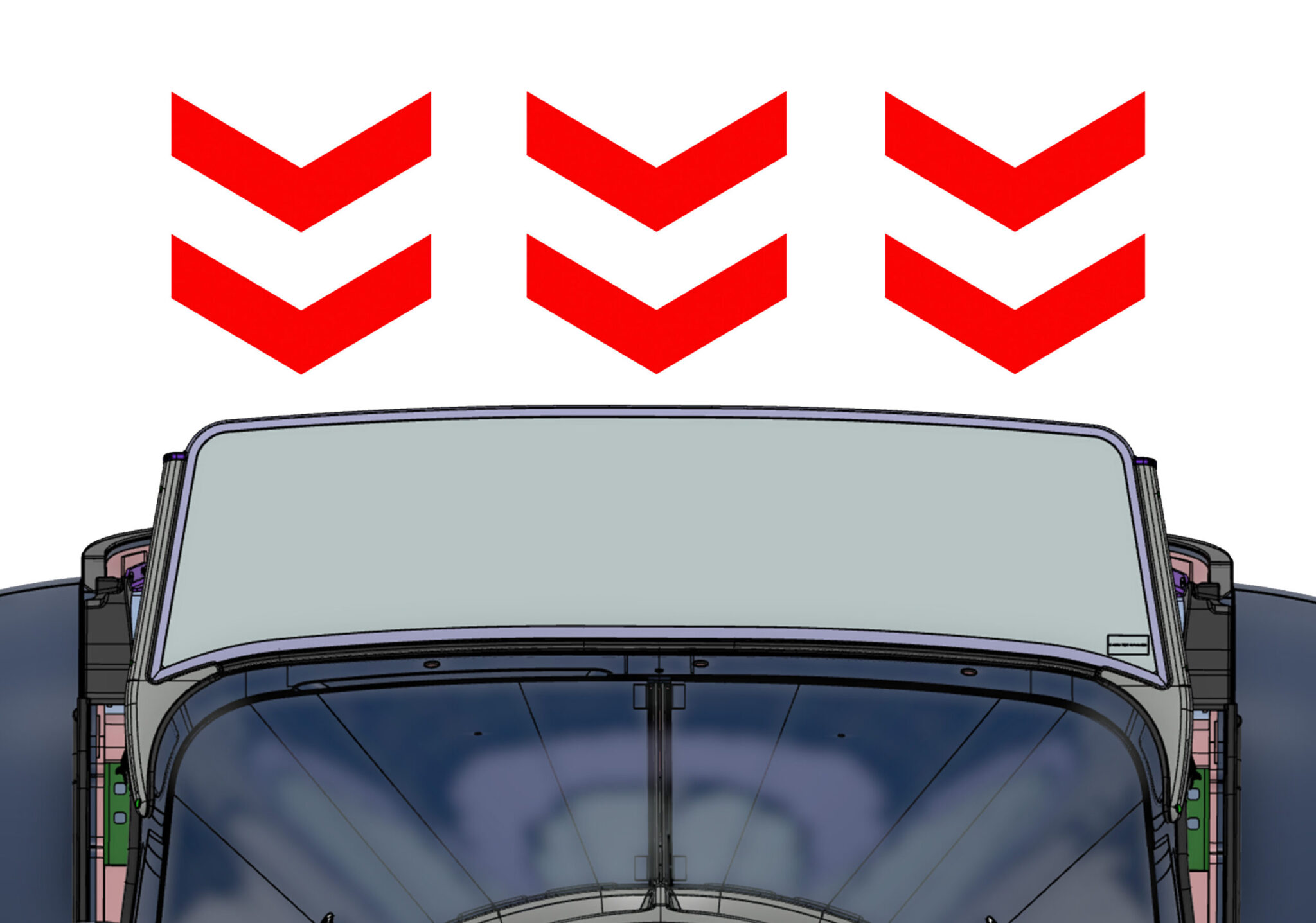
CARE POINT: prep all fixings seen in the next slide before windscreen assembly fitment
Carefully lower the windscreen square to the scuttle and in line with the pre-drilled holes.
Use image for reference.

CARE POINT: Ensure all fixings are fitted at the same time (side to side) & tightened in the sequence numbered in the image.
See image for fixings order.
- x2 m6x30mm dome head bolt (U541012), x2 m6 fibre washer (MGW0014), x2 rubber penny washer (MGW1000), x2 m6 penny washer (MGW0106), x2 m6 nyloc nut (MGN0027).
- x2 m6x30mm cap head bolt (F541031), x2 m6 fibre washer (MGW0014), x2 rubber penny washer (MGW1000), x2 m6 penny washer (MGW0106), x2 m6 nyloc nut (MGN0027).
- x2 m6x20mm flanged hex head bolt (U010017), x2 m6 penny washer (MGW0106), x2 rubber penny washer (MGW1000).
Fit all fixings in sequence and get all to a near tight condition. This will allow for slight movement whilst setting the screen angle.
Use image for reference.
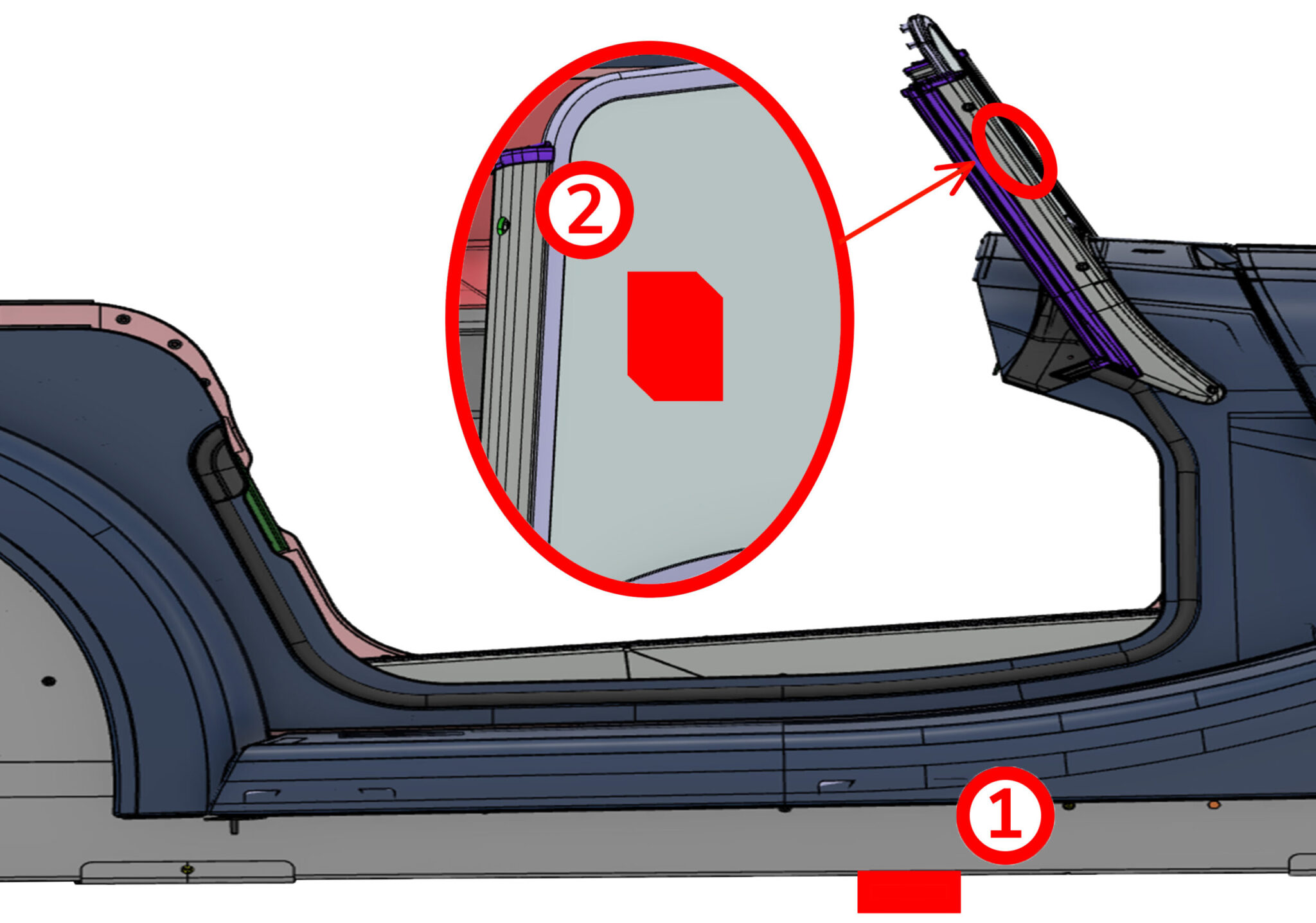
Zero the inclinometer to the underside of the chassis side and place on the windscreen in the area shown.
Produce an angle of 64.5 degrees (+/- 0.5 degrees) on both sides of the windscreen.
Once the angle has been set, use the previous slide and tighten each bolt in sequence. Ensure fixing 3 has blue loctite 2400.
Carefully lower the windscreen square to the scuttle and in line with the pre-drilled holes.
Use image for reference.

Cut x2 pieces of R371012 to 1348mm.
Use image for reference.
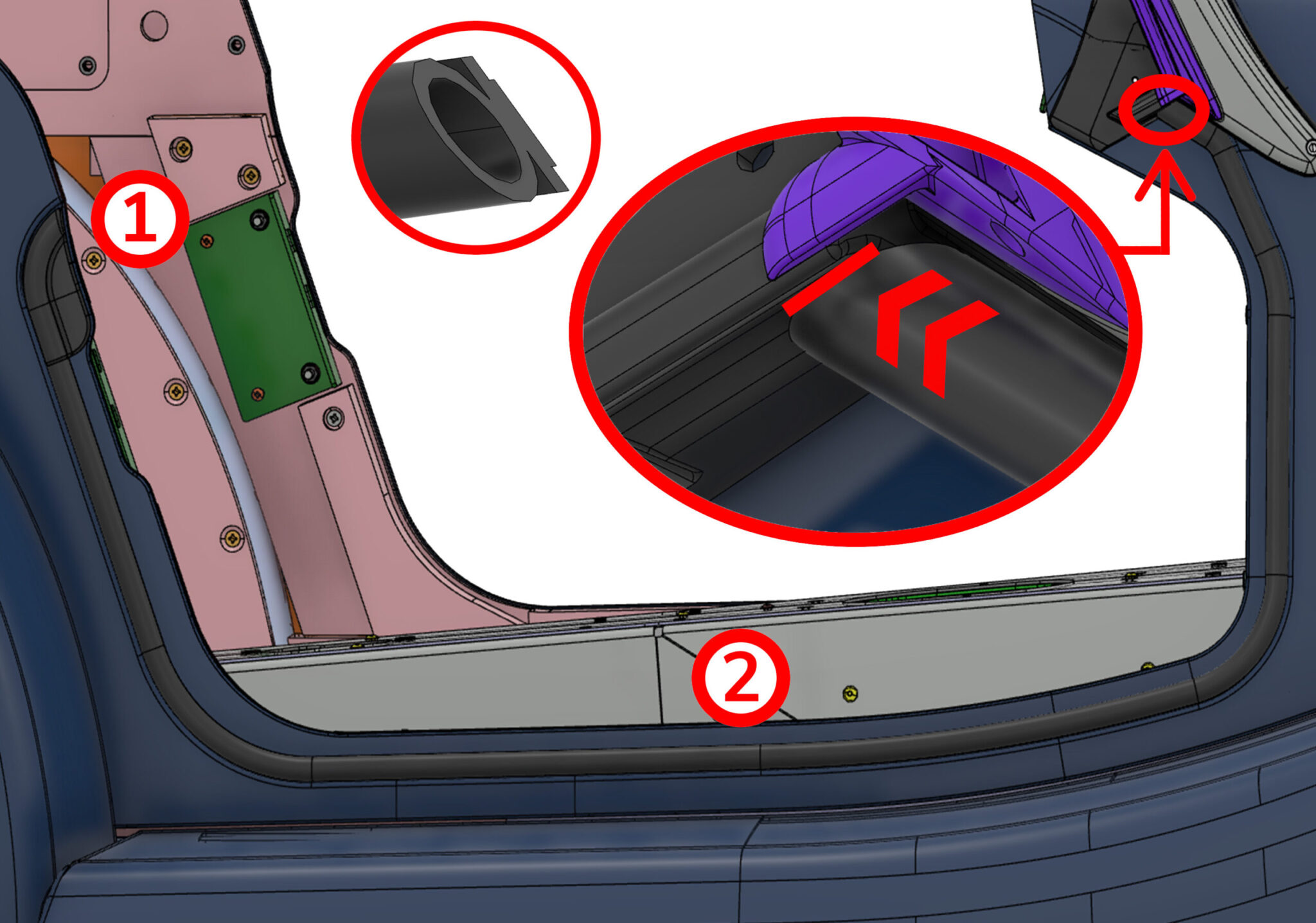
Once the corner seal has been fitted, apply the cut seal in the orientation shown in the diagram.
Use super glue to tack down the primary door seal to the underside of the scuttle seal.
Repeat process on the opposite side assembly.
Use image for reference.

Use work instruction TPI 1 to trim down a set of A-Pillar seals.
Remove all tape film and apply the seal to the A-Pillar.
Repeat process on the opposite side assembly.
Use image for reference.