FRONT SUBFRAME SUB ASSEMBLY
Document Number: SS12
Author: Thomas Sloan Kirton
Date Created:
Revision Number: v1.0.0
Document Approved by:
NOTE. Document is uncontrolled if printed
All instructions in this manual must be adhered to for this stage. Read all instructions carefully and study the photographs. While learning this procedure, quality of work is more important than speed of assembly.
ALL FIXINGS MUST BE FIT IN ACCORDANCE WITH THE TORQUE STANDARD SPECIFICATION SHEET.
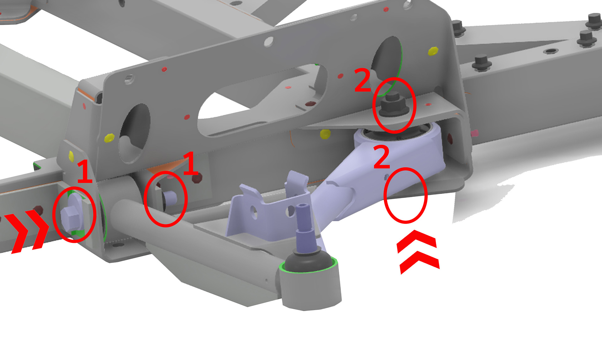
- Fit the lower wishbones to the subframe using:
- x2 CAM bolt (Y161031) & x2 m12 serrated nut (F011143).
- x2 M12x80mm flanged hex bolt (U500063) & x2 m12 locknut (F121005).
- See image for reference.

- Fit both engine mount sub assemblies using x8 m8x20mm flanged hex bolt (U010027).
- See image for reference.
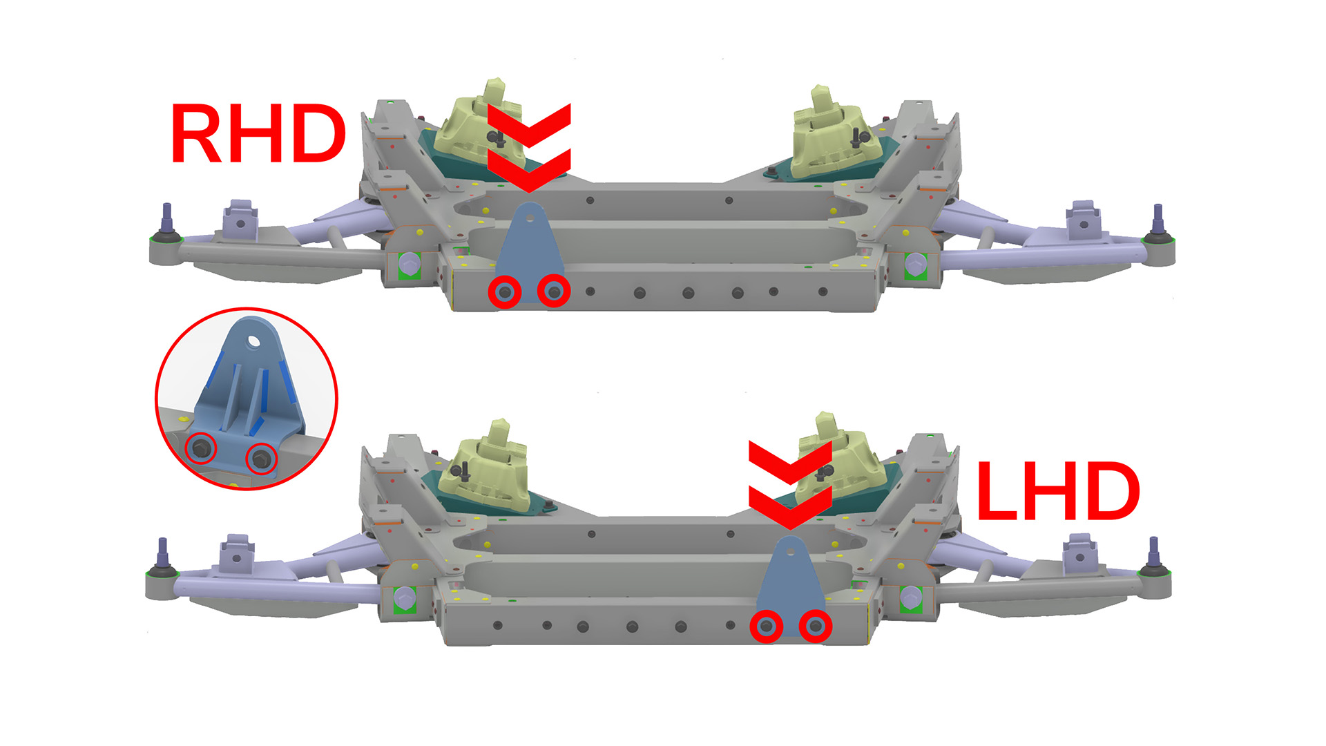
- CARE POINT: Note that the mounting of steering rack mount differs between LHD & RHD models.
- Fix x1 steering rack mount to the subframe using x4 m8x25mm flanged hex bolt (U500064).
- See image for reference.

- CARE POINT: Note that the mounting of steering rack mount & garden gate differs between LHD & RHD models.
- Fix x1 steering rack mount & garden gate to the subframe using x5 m8x25mm flanged hex bolt (U500064).
- See image for reference.
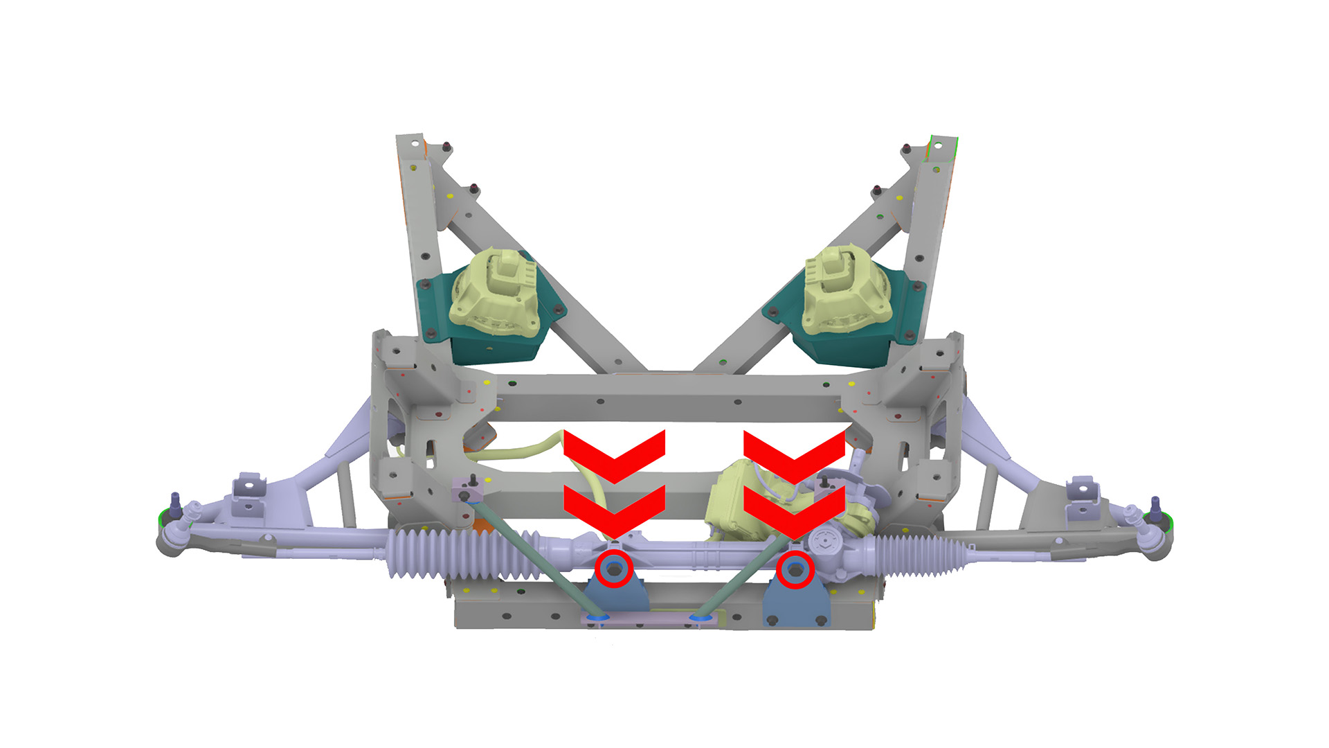
- Fit the steering rack to the sub assembly using x2 m12x50mm hex bolt (F191001) & x2 m12 steel washer (F010038).
- The front subframe is now finished and ready for fitment to chassis.
- See image for reference.