FRONT UPRIGHT SUB ASSEMBLY
Document Number: SS72
Author: Thomas Sloan Kirton
Date Created:
Revision Number: v1.0.0
Document Approved by:
NOTE. Document is uncontrolled if printed
All instructions in this manual must be adhered to for this stage. Read all instructions carefully and study the photographs. While learning this procedure, quality of work is more important than speed of assembly.
ALL FIXINGS MUST BE FIT IN ACCORDANCE WITH THE TORQUE STANDARD SPECIFICATION SHEET.

- Press fit the hub adapter to the wheel bearing.
- CARE POINT: Ensure the rough side is facing upwards when carrying out this step.
- Use image for reference.
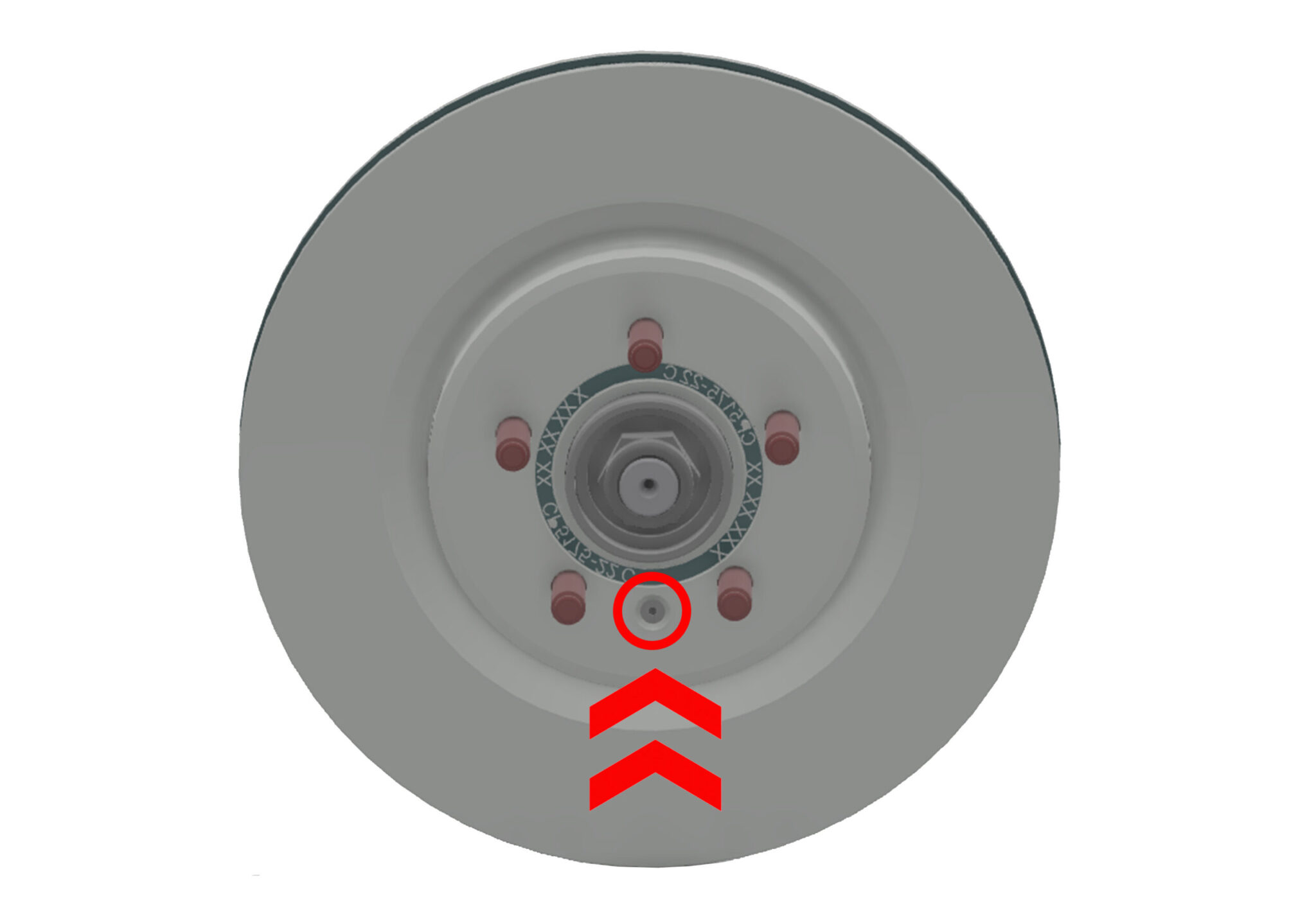
- Fit the brake disc to hub assembly with x1 m6x16mm countersunk bolt (MGS11202) and blue loctite.
- Repeat process for the opposite hand sub assembly.
- CARE POINT: Ensure LHS and RHS discs are specified at this point.
- Use image for reference.

- Fit the upright to the hub & disc assembly with x4 m10x35mm flanged hex head bolts (U221005).
- Repeat process for the opposite hand sub assembly.
- Use image for reference.

- Fit the stub joint with the nyloc nut kitted.
- Repeat process for the opposite hand sub assembly.
- Use image for reference.
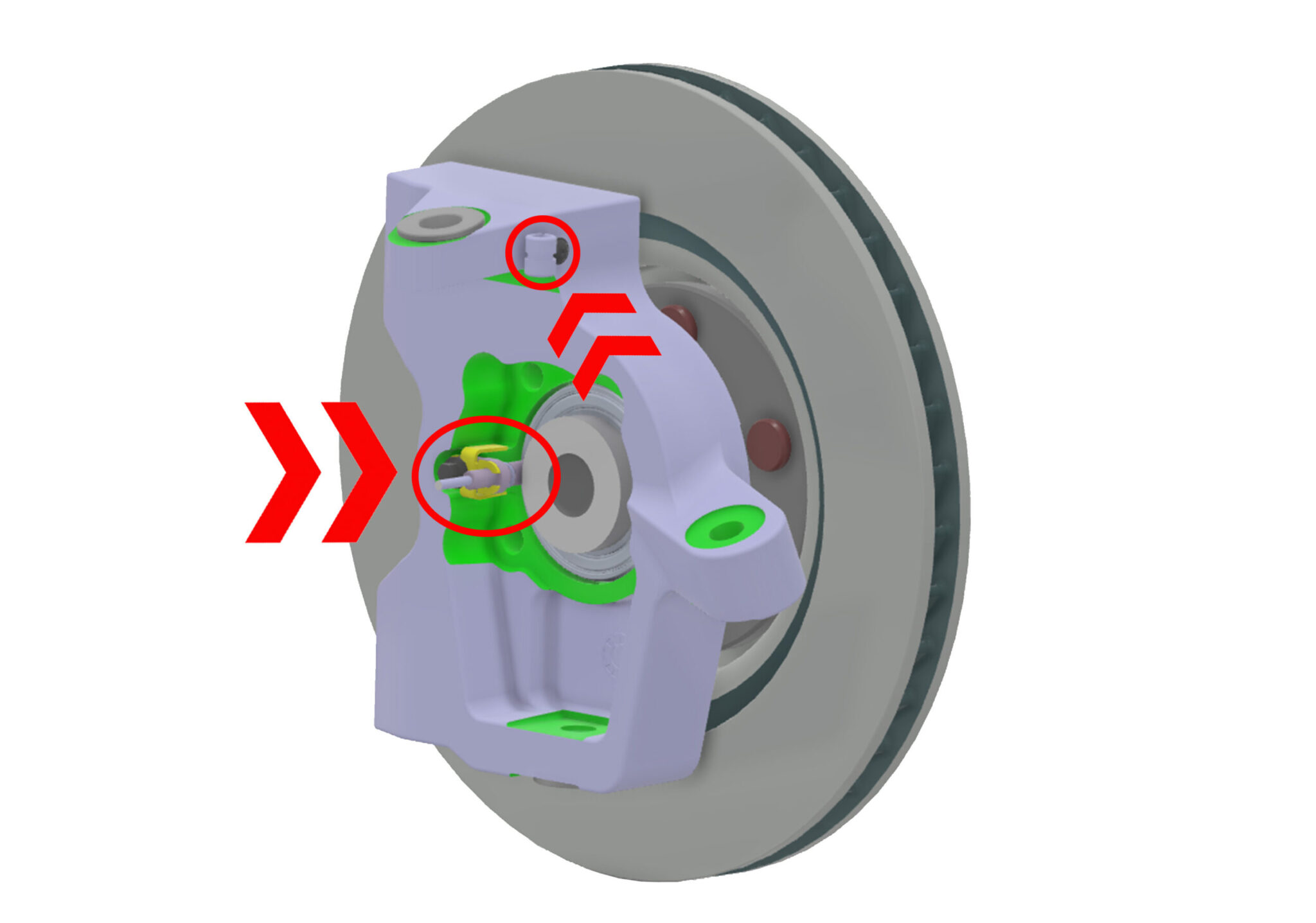
- Fit the wheel speed sensor using bracket B161021 & x1 m6x20mm flanged hex bolt (U010017). Fit the p-clip using x1 flanged button head bolt (F011033). Use blue loctite on both fixings.
- Repeat process for the opposite hand sub assembly.
- Use image for reference.

- After fitment of the pads to the calliper, fit the calliper to the sub assembly using x2 m12x80mm socket cap bolt.
- Repeat process for the opposite hand sub assembly.
- Use image for reference.